How to Choose the Right Mechanical Flange in 2026?
Choosing the right Mechanical Flange in 2026 begins with the service conditions, not the flange label. Pressure, temperature, fluid chemistry, pipe size, and connection type must match. A flange that looks suitable on a warehouse shelf may fail beside a hot pump. Small differences matter.
John H. Bickford, a recognized authority on bolted joints, stated, “The purpose of a bolt is to clamp two or more parts together.” This principle remains practical. A reliable flange connection depends on the flange, gasket, bolts, pipe alignment, and tightening method working as one system. ASME B16.5, ASME B16.47, and EN 1092-1 provide useful dimensional references. However, standards do not replace engineering judgment. Ratings, materials, facing types, bore dimensions, and temperature limits still require verification.
Look closely.
The selection process should compare stainless steel, carbon steel, alloy steel, and lined options against corrosion risks. Raised-face, flat-face, and ring-type-joint designs create different sealing conditions. Gasket compression must suit the flange surface and operating pressure. Bolt preload should follow a controlled procedure, preferably with calibrated tools and documented records. Traceable certificates can strengthen purchasing decisions and maintenance planning.
There is no universal “best” Mechanical Flange. That assumption is convenient, but incomplete. Real projects may involve imperfect pipe alignment, limited installation space, or uncertain maintenance history. These details deserve attention before purchase. A careful review of drawings, manufacturer data, inspection reports, and field experience can prevent costly leakage. The final choice should be technically justified, clearly documented, and checked by a qualified engineer before installation.
What Is a Mechanical Flange and Why Does the Right Choice Matter?
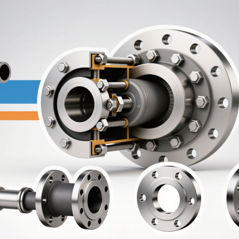
A mechanical flange is a bolted connection that joins pipes, valves, pumps, or equipment. It uses mating faces, bolts, and a gasket to create a controlled seal. The right choice depends on pressure, temperature, fluid chemistry, pipe size, and maintenance access. ASME B16.5 defines common flange dimensions, pressure classes, materials, and pressure-temperature ratings. These details are not decorative. A mismatch can create uneven gasket compression, leakage, or repeated shutdowns.
Small decisions matter.
The U.S. Department of Energy reports that compressed-air leaks can waste 20–30% of compressor output. Flange joints are not the only cause, but poor alignment and damaged gaskets can increase losses. ASME PCC-1 also emphasizes controlled bolting, surface condition, and assembly procedures.
In practice, technicians should inspect flange faces under good lighting, confirm bolt length, and verify the gasket material against the process fluid. A higher pressure class is not automatically safer. It may add cost, weight, and installation difficulty without solving the real problem.
I have found that selection tables can simplify decisions too much. They often overlook vibration, thermal cycling, or limited tool clearance. Recording torque procedures and inspection findings improves reliability, even when the first installation appears successful. Conditions change. That deserves attention.
How to Match Flange Materials with Operating Conditions?
Selecting a mechanical flange starts with the operating conditions, not the catalog photograph. Identify the fluid, pressure, temperature, flow behavior, and surrounding atmosphere. A flange exposed to saltwater spray may fail externally, even when the process fluid is harmless. Carbon steel can suit dry, moderate-temperature service, but moisture and oxygen demand protective measures. Stainless steel often performs better against corrosion, though its resistance depends on chloride levels and temperature.
Heat changes the decision. Repeated heating and cooling can loosen joints through expansion differences between the flange, bolts, gasket, and connected pipe. For elevated temperatures, verify allowable stress and creep resistance from current engineering data. For corrosive chemicals, check concentration, impurities, and cleaning agents rather than relying on the chemical name alone. Duplex and nickel-based materials may improve resistance, but they are not automatically suitable for every process. Details matter.
Material compatibility also includes the bolts and gasket. Dissimilar metals can create galvanic corrosion in wet environments, especially around damaged coatings. In field inspections, small rust marks near bolt holes often reveal trapped water or poor drainage. I have seen specifications focus heavily on internal corrosion while ignoring external exposure. That is an easy mistake. Review operating records, inspect failed joints, and request certified material data before approval. Test before committing. A practical choice balances corrosion resistance, temperature capability, maintenance access, and the cost of an unexpected shutdown.
How to Select the Correct Size, Pressure Rating, and Connection?
Choosing a mechanical flange begins with the pipe, not the flange catalog. Measure the pipe outside diameter, wall thickness, and bore. Match the flange bore closely to prevent turbulence and welding problems. Check the bolt circle, hole count, and gasket seating surface against the mating flange. A small mismatch can cause leakage, even when the nominal diameter looks correct. Confirm the connection type too. Threaded, slip-on, weld-neck, and grooved designs suit different installation conditions.
Pressure rating needs more than a working-pressure label. Review maximum pressure, operating temperature, fluid type, and possible surges. Temperature can reduce allowable pressure. Pulsation and vibration may also demand a stronger assembly. Use the governing design standard and verify its pressure-temperature table. Select bolts, gasket, and flange material as one system. Corrosion, thermal expansion, and galvanic contact deserve attention in wet environments. Do not treat Class 150 and PN16 as automatic equivalents; their dimensions and ratings may differ.
On site, I have seen leaks blamed on bad gaskets when uneven bolt tightening caused the real problem. Use a calibrated torque method and a cross-pattern sequence. Record the flange size, rating, material, gasket type, and torque values. Ask for the latest piping drawing before ordering. It sounds basic. It prevents rework. One judgment call remains: a lighter flange may fit today, but a heavier option could handle future temperature changes better. I would document that decision rather than rely on memory.
How to Verify Mechanical Flange Quality, Compatibility, and Safety?
Choosing the right mechanical flange in 2026 requires more than matching diameter and bolt holes. Verify the material grade, pressure rating, temperature range, and connection standard before ordering. A flange may look correct yet fail because its sealing face does not match the gasket. Check drawings, technical data sheets, and inspection records. Reliable suppliers should provide material certificates, dimensional reports, and pressure-test evidence. Traceable documents matter when safety depends on one small component.
Tips: Measure the pipe outside diameter with calibrated tools. Count bolt holes and confirm their spacing. Inspect the sealing face under strong light. Look for scratches, pitting, distortion, or uneven machining. Compare the flange rating with the system’s maximum pressure and temperature. Never assume a familiar size is automatically compatible. I once trusted a warehouse label without checking the bore, and the mismatch caused unnecessary rework. That mistake still influences my inspection habits.
Safety also depends on installation quality. Use the specified gasket type, clean contact surfaces, and tighten bolts in a cross-pattern. Apply controlled torque when the procedure requires it. Check alignment before loading the joint. Poor alignment can create stress, leakage, or premature failure. After installation, inspect the connection during controlled commissioning. Record measurements, batch details, and test results. Not every inspection catches hidden defects, so independent verification may be sensible for critical systems. Local regulations and approved engineering procedures should guide the final decision.