
What Is a 15kV 200A Loadbreak Junction?
A 15kv 200a Loadbreak Junction is a medium-voltage connection point designed for controlled cable switching and sectionalizing. It commonly links underground cables, transformers, switchgear, and other distribution equipment. The “15 kV” rating identifies its voltage class, while “200 A” indicates its continuous current rating under specified conditions. These figures are essential, but they do not tell the whole story.
The junction normally uses separable connectors, insulated interfaces, and a loadbreak elbow or related accessory. This arrangement lets qualified technicians connect or disconnect equipment without exposing energized conductors directly. The visible parts may look simple, yet internal shielding, contact pressure, grounding, and sealing determine dependable performance. Small installation errors can create heat, moisture entry, or partial discharge.
In practical utility work, technicians check cable size, insulation diameter, fault-duty requirements, and compatibility with the mating equipment. Manufacturer instructions and applicable electrical standards remain authoritative. A product suitable for one 15 kV network may not suit another. That detail is easy to overlook.
Not every 15kv 200a Loadbreak Junction has identical construction. Some models support test points, parking stands, or different bushing interfaces. Selection must match the complete system, not only the label. This article explains its structure, operating purpose, ratings, installation considerations, and maintenance expectations. It also examines common misunderstandings, because a rating alone cannot guarantee safe service. Field experience helps, but careful verification matters more. Even experienced teams can miss an interface mismatch. That deserves reflection.
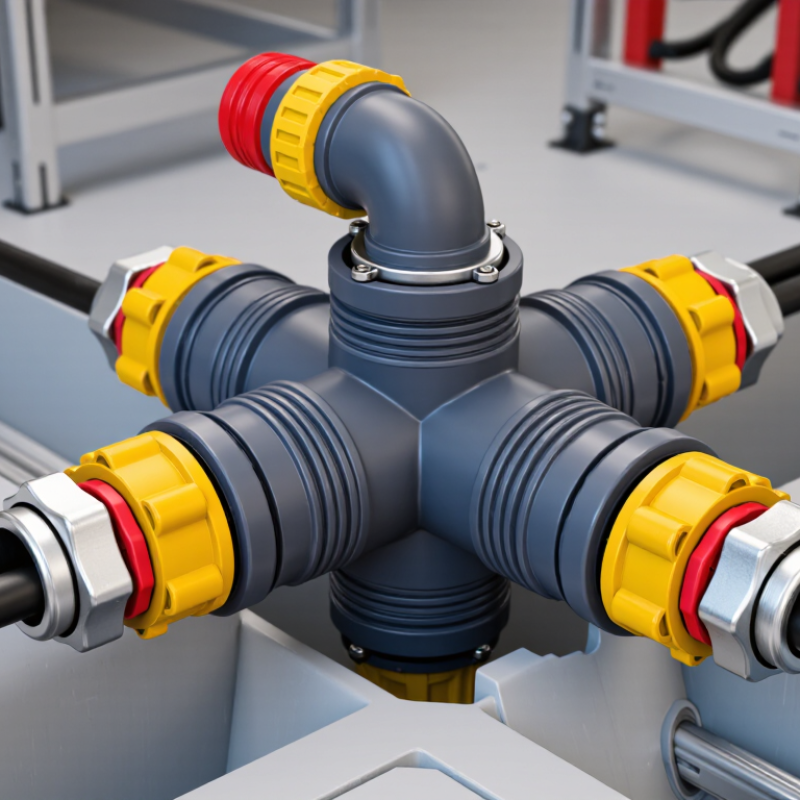
Definition and Purpose of a 15 kV 200 A Loadbreak Junction
What Is a 15kV 200A Loadbreak Junction?
Definition and Purpose of a 15 kV 200 A Loadbreak Junction
A 15 kV 200 A loadbreak junction is a medium-voltage cable connection point. It accepts compatible loadbreak elbows and related separable connectors. The “15 kV” rating identifies its voltage class, while “200 A” indicates its continuous current capacity. The junction creates an accessible connection for underground distribution systems. It can support cable branching, sectionalizing, testing, and equipment replacement. It is not simply a metal connector. Its insulation, interface geometry, and shielding must work together under demanding electrical conditions.
Its main purpose is controlled circuit operation during maintenance or system changes. With an approved loadbreak tool, a trained worker can connect or disconnect a properly rated elbow under permitted load conditions. This reduces unnecessary cable exposure and can shorten service interruptions. However, a loadbreak junction is not automatically a fault interrupter. Its fault-closing and switching ratings must match the complete system design. Field conditions matter. Moisture, contamination, damaged interfaces, or incorrect torque can weaken the connection. A small installation mistake may create a serious reliability problem.
Tips: Confirm voltage, current, fault, and compatibility ratings before installation. Inspect the interface, clean it correctly, and follow the manufacturer’s tested procedure. Use approved insulating equipment and verify the circuit status. Do not rely on appearance alone. A junction may look secure while its internal contact pressure is inadequate. Record inspection results, because maintenance notes often reveal patterns that memory misses.
What Is a 15kV 200A Loadbreak Junction? - Definition and Purpose of a 15 kV 200 A Loadbreak Junction
Reference data table for a medium-voltage cable connection point used to make, extend, branch, test, or isolate 15 kV-class feeder circuits.
| Data Dimension | Typical Rating or Value | Definition and Purpose |
|---|---|---|
| Equipment Type | 15 kV-class, 200 A loadbreak junction | An insulated medium-voltage connection assembly that provides one or more separable cable interfaces for connecting, branching, parking, or isolating energized feeder cables under specified loadbreak conditions. |
| Nominal System Voltage | 15 kV | Intended for distribution systems with a nominal line-to-line voltage of approximately 15 kilovolts. The exact permissible system voltage depends on the equipment design and applicable standard. |
| Maximum Rated Voltage | Typically 15.5 kV for a 15 kV class | Defines the highest system voltage for which the junction is designed. The nameplate and product documentation should be used for the final rating. |
| Continuous Current Rating | 200 A | The maximum continuous current the properly installed junction can carry without exceeding its specified temperature limits under rated conditions. |
| Loadbreak Current Rating | 200 A, when specifically rated | Allows an approved separable connector or elbow interface to interrupt current within its defined loadbreak rating. The junction itself should not be used as a general-purpose switching device unless expressly designed for that function. |
| Power-Frequency Withstand | Commonly 34 kV for a 15 kV class | Indicates the insulation withstand capability during a specified alternating-current test. The actual test voltage and duration must be verified against the applicable standard and product documentation. |
| Basic Insulation Level (BIL) | Commonly 95 kV peak | Represents the impulse-voltage withstand level used to coordinate insulation performance against lightning and switching surges in the distribution system. |
| Operating Frequency | 50 Hz or 60 Hz | Suitable frequency is determined by the electrical network and the assembly’s tested design. Many medium-voltage distribution systems operate at either 50 or 60 hertz. |
| Connection Interface | 200 A separable loadbreak interface | Provides a standardized interface for compatible insulated elbows, plugs, bushings, parking accessories, or test accessories. Compatibility must be confirmed by interface dimensions and ratings. |
| Typical Configuration | Single-sided, two-way, or multi-way junction | The number of connection ports is selected according to the feeder arrangement, such as straight-through connections, loop feeds, taps, or temporary cable parking. |
| Conductor Compatibility | Specified cable size and conductor material | Compatible conductor ranges vary by connector design, cable insulation diameter, conductor material, and compression or shear-bolt termination method. Cable dimensions must be checked before installation. |
| Insulation System | Molded elastomeric insulation with conductive shielding | Provides electrical insulation and a controlled conductive shield around the interface. The shield helps manage electric-field stress and supports safe grounding practices. |
| Shielding and Grounding | Grounded screen or shield connection required | The conductive shield and grounding arrangement help limit touch potential and maintain proper electrical-field control. Installation must follow the manufacturer’s grounding instructions and local safety rules. |
| Primary Purpose | Flexible feeder interconnection | Used to connect distribution cables, create a loop or branch point, facilitate sectionalizing, and provide a practical interface for maintenance or system reconfiguration. |
| Protection Function | Not normally a circuit breaker or fuse | A loadbreak junction provides connection and isolation capability; it normally does not detect faults or automatically interrupt short-circuit current. Separate protective equipment is required. |
| Fault-Current Capability | Design-specific momentary and short-time ratings | Fault withstand values are separate from the 200 A continuous and loadbreak ratings. The required momentary and short-time current ratings must be verified for the network fault level. |
| Applicable Reference | IEEE Std 386 and relevant local requirements | Separable insulated connector systems for medium-voltage distribution commonly use IEEE Std 386 as a technical reference. The applicable edition, utility requirements, and local electrical codes should be confirmed. |
| Installation Environment | Indoor or outdoor distribution equipment, design-dependent | The enclosure, sealing system, contamination performance, and environmental rating determine whether the junction is suitable for pad-mounted, vault, switchgear, or other installation locations. |
| Key Safety Requirement | De-energize, test, ground, and follow approved procedures | Loadbreak capability does not eliminate arc-flash, shock, or induced-voltage hazards. Only qualified personnel using compatible tools, accessories, and procedures should operate or install the equipment. |